
Simple RGB LED driver
Posted by FirmWarez on 7 Nov 2012 in Blog | 1 comment
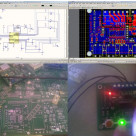
So back on 17 Sept 12 I posted this picture of a board layout on twitter.
This was just a quickie idea I threw together. I had to order a number of protos for customer projects, and decided to get a deal on copper and do a big panel with a number different boards all at once. Boards were in my hands 19 Oct and here we go, on 7 Nov I’ve got some first order code running on my “Simple RGB” board.
The thing is I love LEDs. Serious LEDs. Who doesn’t? What I wanted was simple but flexible RGB driver, that could be used both as a bench test tool and in other applications. After playing with some other processors, I ended up going with a Microchip PIC18F26K80 due to the multiple PWM outputs. I’ve done software PWM before to get multiple channels, but that’s a cumbersome solution compared to hardware PWMs. The board was designed with twin dual channel FETs that can handle 5A. So my “RGB” driver can actually handle four channels; remember, I said I wanted flexible. Power for the processor can be either direct from an outside regulated source or by an on-board regulator. I provided a header with serial port and power pins exposed; this could be used for custom serial control, DMX, MIDI, whatever.
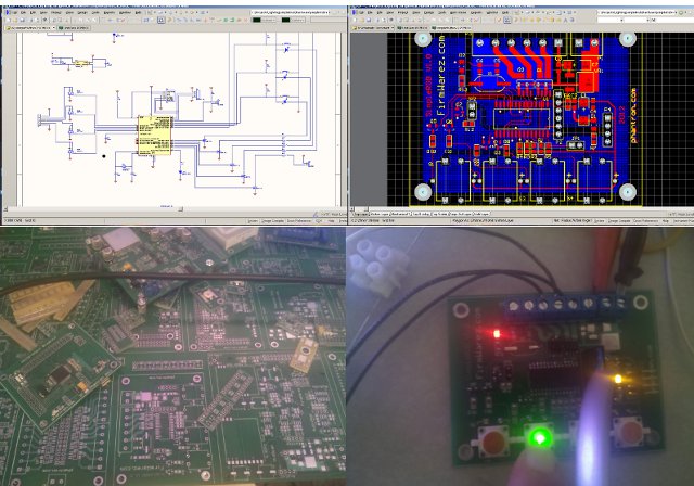
The main interface is via four nifty LED illuminated switches I got from SparkFun. The board has red, green, blue, and orange switches. Basic operation is quickly press a switch to toggle that color from full on to full off, or hold the switch down to run through 256 levels of PWM controlled brightness. I will probably add some functions to the orange switch for toggling between switch controlled, patterns, or ‘random’ colors. In addition to the switches there is a jumper available, perhaps useful for ‘serial’ or ‘switch controlled’ selection. While running in ‘switch controlled’ mode the serial port will output the current PWM settings. That way I can use the board to find colors I like for particular LEDs and then recreate those colors later.
My first tests were with a high output RGB LED I picked up from e-bay. Yes, I’m using big ugly current limiting resistors instead of some more advanced (and efficient) technique. Remember, this is meant to be simple. I’m running the board at 5V, though the 26K80 can run down to 1.8V. My only complaint right now is that the green switch LED isn’t nearly as bright as the others; I may be able to change that with the current limiting resistor.
The board has options for an external crystal. There are surface mount LEDs to indicate power on and one under control of the processor. There is also a small FET and output jumper for control of additional indicators, or whatever.
I’ve got six of these boards on hand. I may make a couple of minor revs and make some more. I’ve considered changing it to incorporate serial, DMX, and MIDI support components, make for a very flexible little driver. I think my hot tub needs more high powered RGB LEDs; that does indeed look cool.
Even though I’ve got a number of client and start-up projects, I like to throw something fun and easy like this in to the mix every now and then. I find it is helpful to have a “success guaranteed” project to keep things flowing. I’m considering releasing this little guy as an open source item. What do you think?
(Ok, ok. The video is awful. I was fighting with focus the whole time because the high brightness LEDs kept messing with the camera. Excuses, excuses. If I didn’t need to get back on other projects I’d reshoot, but customers pay the bills! I’m still putting this up here, my next vid will be better!)
« if your title is “VP”, you probably shouldn’t be fucking with your engineers’ computers | SkyDogCon follow-up »
One comment
Leave a Reply
You must be logged in to post a comment.
I KNEW you were the one behind the Max Headroom Pirate Incident! The truth is now out there